Sound propagation outside...
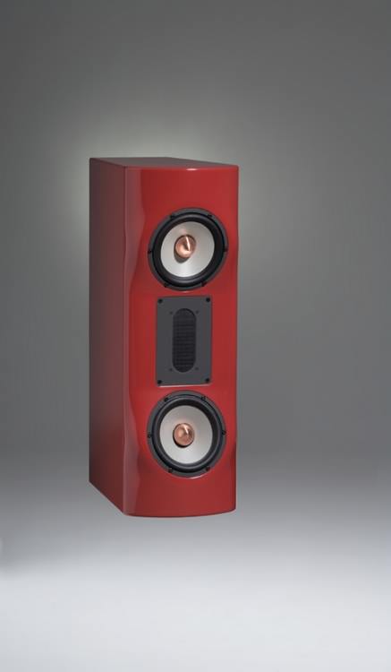
Even in ancient textbooks there were frequency response illustrations for different cabinet shapes. Best are all shapes that have a large roundness from the sound source (the loudspeaker chassis). It doesn't help much to make the side walls decoratively round. The immediate vicinity of the drivers must not have edges, but should have large curves. Here, in the immediate vicinity of the sound source, the sound pressure is highest and the diffraction effects most pronounced.
Sound waves are density fluctuations of particles in the air. When a propagating sound wave travels along a boundary surface (e.g. baffle) and abruptly propagates along an enclosure edge, so-called secondary sound sources are created. These propagate from their point of origin and cause interference with the original wave. The result is an uneven frequency response with sound propagating unevenly at different radiation angles. The secondary sound waves also travel back to the drivers and cause changes in the radiation resistance in front of the diaphragms.
In loudspeaker design, a lot of thought is therefore given to the sound propagation at the cabinet body. Sound waves should be able to propagate without abrupt pressure changes and the resulting secondary sound waves.
This is comparable to the aerodynamics of cars or airplanes. In the mid-high range, the wavelengths of the sound are so short that they lie within the dimensions of the cabinet. Curves in the area of the midrange and tweeter therefore ensure excellent omnidirectional sound distribution. Especially the near edges play an important role. Alternatively, rounded edges and several corners can replace a large rounding. The chamfers on the edges of the Myro Amur Series, together with the 108 degree internal angle of the sides, give almost the same characteristics as a very large rounding radius. Previous tests have shown that a radius of 10 cm gives excellent results.
As a result, the sound image unfolds undisturbed, without time-displaced secondary sound waves. The result is an artifact-free, completely clear sound image.
The Fairy Tale of the Narrow Baffle
Many loudspeaker cabinets have sharp edges or insufficient edge roundings or chamfers near the drivers (e.g. baffle edges). Here, the design desire of narrow cabinets and cheap manufacturing take precedence over acoustics. A narrow baffle is only a good baffle if it merges into large curves, in which case one can no longer really speak of a narrow baffle. The timeless Bauhaus design with its simple geometries is a welcome argument for marketing strategists and pleases the product manager because of the low production costs. However, from an acoustic point of view, these cabinet shapes are among the worst.
Conclusion: The closer an edge is to the sound source, the stronger the effect.

Myro Whisky
|
Sound propagation inside...
For the backward radiated sound the same applies in principle as outside. In addition, there are very energetic reflections inside. This must be prevented by the housing construction. In addition, the interior acoustics determine the spring-mass system of the chassis. To avoid unwanted resonances (standing waves) in the enclosure, parallel enclosure walls are avoided such as by polygons or curves. To suppress the formation of a longitudinal resonance (inner height) is a difficult task with slim, high cabinets. By design, this basic shape always results in an inner height whose resonance can no longer be absorbed by insulation several centimetres thick. Thicker damping materials would fill the cavity and hinder the effect of a bass reflex design. In this case a trick can be found by using and arranging several bass reflex tubes. In this case the air column inside is tapped at different points.

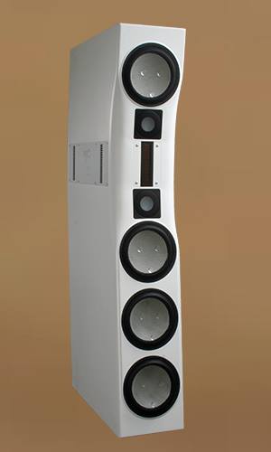
Myro Time 2
|
The arrangement of the chassis
The choice of chassis and the enclosure design with its acoustic and visual features must be thought out together. Myro has experience with signal-directed conversion since 1988. Just finding a fundamentally possible combination of loudspeaker chassis is a difficult, often seemingly impossible, undertaking. If the chassis combination does not fit by itself, a mediocre or even bad result is inevitable. When choosing the chassis combination, one has to consider the required installation situation in the cabinet. At the same time one must have an idea for the crossover circuit in mind and an idea of the desired dispersion behaviour. Every mistake excludes a correctly functioning result. To radiate all sound components to the listening position at the same time is the purpose of a curved or slanted baffle. If you look closely, you'll notice that the woofers are a few millimetres further forward than the midrange domes. When reproducing impulses, millimetres decide whether the sound components of all systems fit together and form the correct sum at the same time.
In practice the interference range of the drivers with flat filters and specialized drivers (tweeter, midrange, woofer) is usually narrower than one usually assumes. The drivers normally leave just above and below the crossover frequency with 18 dB/octave or 12 dB/oct. through the driver plus (for example) 1st order filter (6 dB/oct.). These steep slopes are a big problem with analog loudspeakers because of the strong phase rotation in relation to the goal of the in-phase, synchronous transient, the formation of the original sound form. Interference problems occur primarily due to non-symmetrical chassis arrangement, chassis distances that are too large in relation to the jointly radiated frequency, and the aforementioned phase rotations.
Wide overlapping ranges with linear flanks and minimal phase rotations are relatively unproblematic, as long as the symmetrical arrangement and the sufficiently small distances are maintained. The summation then works so well that clean signal shapes result.
If one finds the right mixture with regard to the mentioned factors, a good radiation behaviour for the perception of the listener in the listening area is achievable. And this without having to do without the correct conversion of the sound signals.
- If the drivers are arranged vertically, frequency response irregularities will occur at vertical dispersion angles if the driver distances are large against the wavelength.
- If the drivers are arranged vertically, frequency response irregularities will occur at horizontal dispersion angles if the directivity of the drivers is not balanced by their overlapping.
Basically, the frequency response deviations under angles are relative to the frequency response on axis.
In the case of vertical chassis arrangement, another aspect arises for the vertical radiation pattern. If we look at the sound reproduction of the transients, steep-sided transitions with non-symmetrical chassis arrangements are usually even inferior to symmetrical arrangements with flatter transitions. So, all in all, it's a question of balancing the factors - and the user's expected set-up conditions for a loudspeaker concept. Each application requires a radiation pattern that is tailored to the specific installation conditions. Even the so-called point sources show a lot of irregularities in the radiation behaviour.
|
Sound lines
To arrange tweeter sound lines and midrange sound lines next to each other is nonsense. This also applies to individual drivers, which are therefore never arranged horizontally next to each other on the baffle at Myro. If you look at the rising edge of an impulse at different horizontal angles, you will notice that the different distances to the sound sources result in different sound propagation times. The rising edges of the tweeter and midrange sound line (or chassis) arrive with a time delay and can never form the original sound wave. This is particularly critical on the horizontal plane because the seats in the room are distributed horizontally, as armchairs are not on top of each other but side by side. In addition, we listen with two ears that are horizontal to the head. At least one of the ears would receive distorted transients.
Even with a horizontally symmetrical array, these distorted transients result. These systems are all designed for transient conditions, with chassis spacing and co-transmitted wavelengths playing a role. These are pure sound pressure distribution aspects. The transient response of these systems is distorted.
The surface
It is a "lacquer art" to create a surface without ripples with a fine velvety finish. The sense at what degree of drying of a lacquer layer the next layer must be applied is one of the secrets of good piano lacquer surfaces. The lacquer layer has a thickness of ≈1.2 - 1.4 mm. This must be taken into account when milling out the openings or recesses in the chassis.
Compared to silk matt or matt lacquers, high gloss lacquer has the advantage that it can be polished. Spray mist, which is deposited on the rear sides of bodies when they are painted, can be polished away. With matt paints, shiny spots would result immediately. The same applies to abrasion, e.g. during transport or when cleaning the surface. That's why Myro and Michael Weidlich Audio prefer piano lacquer surfaces. The costs for this surface quality are of course higher.
<zurück: Myroklopädie>
<zurück: Myro>

