The Swing-in
|
A loudspeaker tries to reproduce transients by transient oscillation. This transient response occurs according to its transfer function, provided there are no nonlinearities, e.g. resonances. Chassis behave completely differently when reproducing a first half-wave than they do when transient. This is due to the inability of electroacoustic transducers to fully reproduce the first half-wave of an oscillation (e.g. sine, sine burst, or even music signal). Strictly speaking, a chassis can only reproduce the first half-wave with the correct frequency at exactly one single frequency! The transfer function describes the transient response and the difference between the first and the following half-waves, the quasi-swinged state. It is characterized by a high pass in the woofer and a low pass in the tweeter, both of which determine the limits of the bandwidth of the loudspeaker. And both show an opposite behavior in the transient distortion of the signals. This means that during transient response the low frequencies (= high pass) and the high frequencies (= low pass) are cut off and the speaker has a lower bandwidth than the frequency response shows. In the case of complex resonance phenomena, however, a simple transfer function fails completely. In principle, a loudspeaker can only transpose correctly over the entire (or its average) bandwidth, if it shows a rectangular or rectangle-like behaviour. Only then would the first half-waves within this bandwidth be correct in amplitude and phase. |
For the most part, it is assumed that the loudspeaker will transient on jump excitation such that it exhibits the characteristics (frequency response, etc.) that it exhibits when transient. This is not the case! For the steady state characteristic (amplitude), the complete oscillation process is necessary until the steady state is reached. If however already after reaching the first maximum voltage value of the jump no voltage change in the sense of alternating voltage is present, the drive of the chassis ends with it. In nature there are such excitations, for example:
- explosions, gun shots, etc.
- percussion instruments with vibration damping (hardly any reverberation)
- hand clapping / applause
- and many more.
The chassis then only resonates over or after. It does this in the direction of its resonance frequency, but without emitting any significant sound pressure, especially none that is added a few milliseconds later. Therefore, the response of the driver is completed much sooner. If you excite a loudspeaker with a jumpy waveform without any further oscillations, it will not reach the steady state either and all the models that assume this do not apply. The "backward oscillation" with the zero crossing at completely accelerated mass is missing and thus the complete oscillation of the spring-mass system. Only when this process has been passed, one can speak of a steady state. Some loudspeakers reach this (depending on the quality) even later.
ContentsTweeterThe dynamic music signal is all about speed. The rising edges and times of the impulses depend on the ability of the tweeter to settle extremely quickly. In the case of the tweeter, at the upper transmission end, the resonant frequency of the diaphragm is particularly crucial. But if a tweeter transmits very high frequencies in the frequency response diagram, this does not mean that it is fast. With many tweeters the frequency response is only up to 20 kHz because the low pass and the diaphragm resonance have been tuned in such a way that the result is an almost linear response in the steady state. This can be seen by a steep drop above the resonance frequency, i.e. at the end of the frequency range visible in the frequency response. A high treble level, caused by the diaphragm resonance, has to settle down first, and that takes two to three half waves! However, the signal / time response usually looks bad from 5 to 10 kHz. 'What quality must a transmission line have if a person consciously perceives 16 kHz without restriction?" Remarkable are the specifications of the upper cut-off frequency (-3 dB) by some manufacturers. For example, an upper cut-off frequency of 100 kHz is declared for the Accuton BD20 (20 mm diamond cone). In fact, however, according to measurements by the driver manufacturer, the -3 dB point is at ≈ 44 kHz, but this is without a main diaphragm resonance overlapping.
This is at ≈ 60 kHz (about -10 dB point / depending on the mic). The manufacturer has therefore "glossed over" the 100 kHz by more than an octave! |
wooferIn the low bass range, we are at the physical limits of the transducers, which are limited in their geometric dimensions, and the enclosures necessary to avoid acoustic short circuits. To produce deep bass is a trivial task for a loudspeaker designer. But finding a customer for such a large speaker is a very difficult task. There are always restrictions on the part of the user concerning the size of a loudspeaker and also concerning the price. The "ideal" of the small, slim, pretty floorstanding speaker has the consequence that if one wants to meet this not insignificant demand, with these physical limitations one can in principle build a loudspeaker that is correct in time (simultaneity of transient response and linear phase), but these speakers lack the ability to produce bass dynamics that do justice to the dynamics of the mid-high range (cf. first half wave). But forcing woofers with large amplifier power to reproduce low bass against the high compression of small enclosure volumes not only deforms their diaphragm, but also heats their voice coils. Hot voice coils become even more highly resistive with each burst of heat. That's built-in compression, since amplifiers deliver less power to high-impedance loads. You also have to think of it in terms of rhythm. So keeping the frequency response in the bass at a high level is not the problem, but the transient, the impulse dynamics is.
the function of the mechanical oscillating system (resonance frequency)
The spring-mass system plays a crucial role in the formation of the first half-wave. It is tensioned (energy storage) and acts in the opposite direction to the drive direction. At the point where the drive energy and counterforce of the spring-mass system are equal, only the energy of the moving mass causes a brief further forward movement. This (system resonance), together with the radiation resistance, produces the high-pass characteristic. |
|
|
|
Example: |
With all cabinet tunings that make use of a resonant system (e.g. bass reflex, transmission line, etc.) to amplify the bass sound pressure, this illusion is even much greater! A resonant system needs several half-waves to resonate and add additional sound pressure. The behaviour corresponds to the transfer function. However, the first half-waves are not stronger than in a closed cabinet, because here the resonance behaviour is not yet effective. It shows that there is a serious difference between the transient and the steady state.
The Bandpass
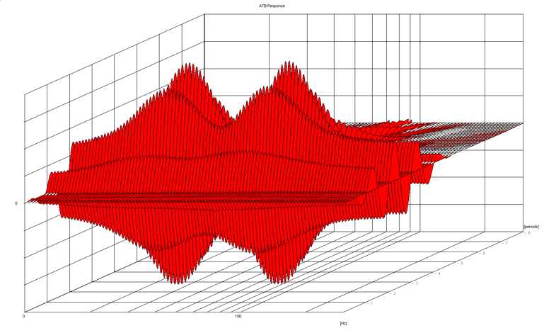
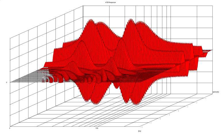
Basically, a bandpass oscillates extremely slowly. The amplitude shown in the frequency response is only reached after several half-waves (at the earliest from the third half-wave, although this is continuously increasing). Even if you would place a bandpass loudspeaker in such a way that the generated sound wave would start at the same time as the mid-high segment, in many cases you would have problems with an antiphase polarity. Helpful for the metrological representation of the transient response are, besides the not so easy to interpret step response, the front view of waterfall diagrams or even more descriptive, oscilloscope measurements with sinus bursts.
Let's look at the transient response of instruments and sounds: In natural sound events, the first half-waves are usually the loudest. The following half waves become quieter more or less quickly. Thus we have an unnatural, opposite behaviour with loudspeakers. This is even more unnatural with cabinet tuning with additional resonance system, because the ratio of first to following half waves becomes even more opposite. The better the overall phase response of a loudspeaker becomes in the mid and upper range (also in the transient), the more the bad behaviour towards low tones becomes noticeable.
Even in a closed cabinet the drivers have a delayed transient response. Regardless of the enclosure / tuning principle, the first half-waves have a high-pass characteristic that is practically always the same, which in principle corresponds to the effective part of the radiation impedance.
The bass reflex system'
Transient response of a multi-way loudspeaker
From the frequency from which a chassis reaches the matching to the air, the chassis can already reproduce the first half wave with full amplitude and correct zero spacing (corresponding to the input frequency). Therefore, in this range (up to the low pass) a linear phase reproduction can be realized. And with multiple paths the range can be extended, depending on the high pass of the woofer and the low pass of the tweeter. The loudspeaker has a linear-phase range and a minimum-phase range in the low-pass and high-pass regions. Therefore, rectangles can be reproduced in certain transmission ranges.
|
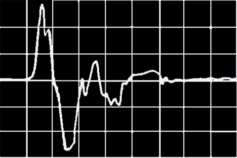
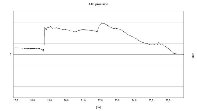
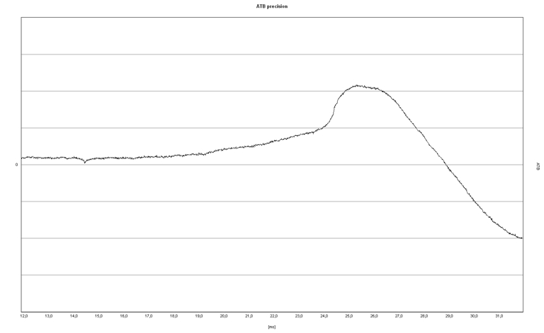
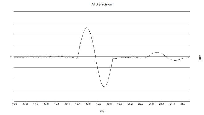
On the left is an actual example of a digital speaker from a very reputable company. The humps / waves starting at 20.5 ms are due to initial reflections. | |
|
The reproduction of a 1,000 Hz sine wave (1 period) looks like this. | |
|
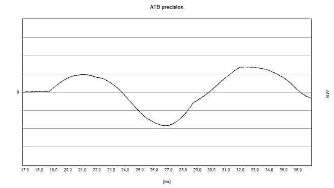
At 100 Hz, however, this behavior is long gone. The first half wave does not have the full amplitude and not the full duration. The loudspeaker behaves again like a typical minimum phase system with a correspondingly decreasing step response. As an aside, there are again very strange digital artifacts to be seen: There are straight sections in the half waves. Whether these are errors in the calculation or fundamental problems in the attempt of a linear group delay is still unclear. |
What can be technically corrected?
Digitally...
the group delay can be equalized, but the problem of the missing amplitude always remains in the transient - in the period, where the radiation resistance curve sets the basic conditions, before the resonance case occurs. A group delay correction alone does not result in a correct signal conversion! This is because the signal contains a sequence of pressure fluctuations (pressure values). The group delay error is caused by the imperfect transient response due to the laws of physics. The first half wave is not fully formed by bass speakers, i.e. the first zero crossing occurs well before 180 degrees. The bass is leading! Filters delay with increasing order increasingly in the range of the low pass. This contains a clear amplitude error. However, it is physically impossible to achieve the correct time-amplitude relationships in the limit ranges of the transmission system. If one wanted to correct the pressure-time error of the transient, one would have to push so much energy into the systems transient that the drivers would be destroyed or the bass would make an extreme excursion across the room. And even that would not help.
|
Another problem is shown by the following measurement of a woofer that oscillates at 40 Hz (sine). A chassis control first requires the acquisition of a certain amount of data in order to be able to apply mathematics at all. The digital control starts accordingly delayed. After a certain time, it recognizes the deviation of the actual from the target, sets in and readjusts. However, the process takes place visibly abruptly and therefore contains (spectral analysis) significantly higher frequencies. What remains is the practical maximum size of the diaphragm area and the required construction, to be determined by each individual. For these individual requirements loudspeakers have to be developed in corresponding, always limited sizes. And these should convert as correctly as possible within the physically possible transmission range. |
|
Control by analog sensor Similarly problematic is the correction of room induced cancellations. Regulation brings advantages at the lower transmission end, especially in the steady state. However, the steady state is completely subject to room resonance problems in the bass, with all the effects and limitations of attempting correction. Directly diaphragm controlled basses ignore changes in the radiation resistance of the room and therefore excite modes more than unregulated speakers or even microphonically controlled ones. This is because the controlled loudspeaker doesn't act as a "soft bass trap" but as a "hard wall" with regard to any external excitation of the diaphragm that doesn't succeed. However, the difference to unregulated loudspeakers is only slight, as there is an extreme acoustic mismatch. In the bass you would have to correct the room, otherwise it makes no sense. But this is only possible to a very limited extent, and if so - for which space in the room? In addition, room resonances easily cause 10 dB amplitude fluctuations. That's mighty compared to the effect of a control. So the detector must be at the listening position! In the middle and especially in the upper transmission range of a chassis the manifold resonance phenomena (membrane resonances, resonances of or with the spider and with the edge suspension etc.) can no longer be detected inductively. The resonances no longer have a clear effect on the drive system with their kinetic energy. A control is therefore no longer possible in a meaningful way in the largest part of the transmission range. A control system works better here. |
|
<zurück: Myroklopädie>
<zurück: Myro>
