Template:Delete candidate
|
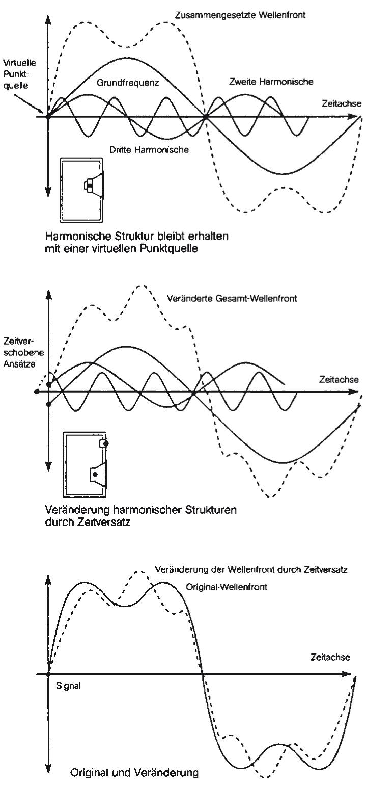
For the simultaneous addition of the sound components of the individual drivers at the listening position, identical distances / travel times of the various acoustic centers to the ear are mandatory. The elementary prerequisite for the correct summation is the simultaneous start of the sound events. The sound of the tweeter and the sound of the midrange / bass drivers must start at exactly the same time. In three-way constructions this also applies to the woofer. It applies to multi-way systems and also to one-way loudspeakers, e.g. broad-range drivers, where different acoustic centres are formed on the diaphragm at different frequencies. The distance and thus the time of flight of all acoustic centers to the listening / measurement location must be identical, so that the sound components are time-synchronous and can overlap properly.
In practice, there is usually a depth offset of the acoustic centers in loudspeaker systems due to the design. The acoustic center is the point from which all of the sound generated appears to emanate. It is a virtual, imaginary point that can only be precisely determined by measurement. The location of the acoustic center depends on various design conditions. The stiffness of the voice coil former, the diaphragm and its geometry (and others) play a role. The softer the diaphragm, the lower the acoustic center. The sound origination points are located near the voice coil leading edge of drivers in the usable transmission range, i.e. where the diaphragms do not break up into chaotic partial vibrations. For easy orientation one can assume the junction of the voice coil with the diaphragm as the acoustic center.
For tweeters, the acoustic center is relatively far forward; for woofers, it is up to several inches behind the leading edge. (With the very hard Accuton ceramic diaphragms, the acoustic center of a 20 cm woofer is about the same as a 17 cm chassis made of other material. In the Accuton Cell Series, on the other hand, the acoustic centers of the drivers are exceptionally precisely matched.) However, outside the drivers' useful range of use, multiple acoustic centers occur on the diaphragm as a function of frequency, with corresponding time-of-flight differences and interference.
If one were to draw an arc around the ear with a compass, all acoustic centers of the loudspeaker systems would have to lie on the arc in order to be exactly equidistant from the center (the ear). Millimeters are what matters here. Thus the running time is the same and a correct summation is possible under this elementary aspect. If this is not the case, the simultaneous arrival of the sound components and their correct summation is not possible, the loudspeaker distorts the sound signals and produces artificial noises. The faithful reproduction no longer takes place.
If the loudspeaker fulfils this criterion due to its design, this results in a corresponding, correct listening axis from the listener's ear to the distance centre of the connecting line of the acoustic centres of the drivers, especially the high-midrange drivers. For example, if we connect the acoustic centers of two chassis and the perpendicular at the center of the connecting line points to the ear of the listener, the simultaneous addition of the sound components is possible. Along this perpendicular we now get listening or microphone positions with equal travel times to the chassis. In case of a vertical chassis arrangement, the correct summation of the sound structures radiated by the individual chassis in relation to the time synchronization only results on this vertical, with a certain horizontal span (horizontal plane).
|
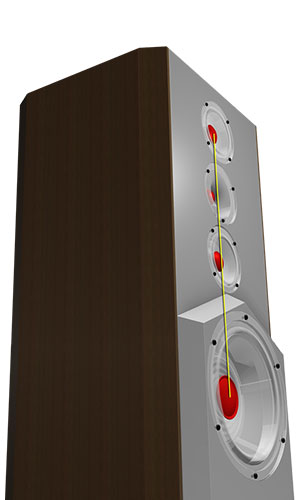
The precisely tuned position of the acoustic centers (red) of the drivers in the Genuin Pulse using a stepped baffle.
|
Myro a priori 10.02
|
If we now approach the loudspeaker on this perpendicular (time synchronisation axis / plane) with our listening / measuring position, the phenomenon of sound bundling due to the chassis' own directional characteristics also arises in the case of the design-related run-time correct chassis positioning. (The directional characteristic of the chassis results essentially from their membrane diameter and the membrane geometry as well as the fast-dependent directional orientation of the air particles.) This criterion prevents a transferability of the near distance results to the practical longer listening distances.
- With two acoustic centers, there is a time synchronization axis.
- With three acoustic centers there are two time synchronization axes.
etc.
However, an auditory / measurement point cannot lie on two axes at the same time. From all this follows:
Time-synchronous summation is only possible with two acoustic centers at close range, but the sum is not transferable to larger practical distances due to the directional characteristics of the drivers. With two acoustic centers and one close-range measurement point (approx. 1 m distance) on the time synchronization plane and assuming no directional characteristic problems, the results are approximately transferable to larger distances, neglecting the frequency-dependent attenuation of the air.
In the case of three or more acoustic centers, the correct summation at close range is impossible - especially also with simultaneous transferability to other distances. In this case, if the acoustic centers are arranged vertically, correct summation is only possible on one horizontal segment of a circle in front of the loudspeaker. This means that with three or more acoustic centres a correct summation of the starting edges must be carried out at a greater distance, ideally at the listening position.
Vertical one always has the delay error of the time-shifted starting edges of the individual drivers. With steep filters the overlap is smaller and the sum is more similar to a sawtooth. With flat filters there is the same delay error, but with a more slurred sum pattern. This tends to sound less aggressive. But both are wrong.
As the distance increases, the synchronization problems of the starting edges of a sound shape decrease because the angular distance differences become smaller.
The only way to keep the point of in-phase sound addition as close as possible to the loudspeaker is to have an acoustic center, and here the directivity is even more important. If we listen or measure close in front of a loudspeaker, three-way constructions inevitably (two-way constructions in sensitive dependence on the ear / microphone position) result in distance and thus delay differences to the individual systems. In the borderline case we have, for example, with a microphone position directly in front of the tweeter a distance difference in the order of magnitude of the distance to the acoustic centre of the midrange driver. This results in a considerable delay difference for the summation. Depending on the distance difference to the microphone, the starting points are then already so far apart that the sound components of the tweeter and mid-woofer are no longer on top of each other.
Another problem with short distances are the angle changes to the different drivers. In the previous boundary case consideration we would have 0° to the tweeter and almost 90° to the midrange driver. The midrange driver bundles with increasing frequency. So nothing fits together anymore.
|
With increasing distance of the listening position to the loudspeaker the mentioned problems decrease. This fits to the actual application. If the acoustic centers of the chassis result in different travel times to the listening or measurement location due to the design, the correct summation is impossible. (Exception: with digital delay circuit) To exclude a possible thought error: All this is basically independent of the crossover design.
And even digital delays for the purpose of time synchronization of the step responses of individual drivers can only refer to a single measurement point. The aspects of boundary case consideration also apply here. The transfer characteristics of the individual drivers and the crossover design determine whether the pressure-time summation is correct from the starting point, the initial point of the sound event. That is another, much more difficult chapter.
- Coaxial speakers or other designs with extremely close acoustic centers allow for shorter listening / measuring distances than multi-way systems with more widely spaced acoustic centers. As a rule, they only show an acceptable transmission response between 15 - 20 degrees off-axis, and there are virtually none that can be tuned in analogue time. In the case of coaxial loudspeakers, the acoustic centres of the individual systems must necessarily be at the same height, otherwise time-synchronous sound addition is generally impossible. Exception, as in all other cases: digital technology with delay, whereby this also only applies at one reference point (with three acoustic centres) or on one reference axis (with two acoustic centres). Coaxial loudspeakers also always have the problem of a low-midrange stroke-induced moving sound environment of the tweeter. In addition, the diaphragm resonances of the drivers are extremely excited by the extreme sound pressures of the close neighboring systems from the outside. Hard diaphragms with usually mechanically undamped diaphragm resonances are not suitable here.
- Manger recommends for his Manger transducer a minimum distance for the formation of a coherent sound wave.
- Full range surface radiators are particularly often affected by partial oscillations. They form multiple acoustic centers on the diaphragm at higher frequencies. Many vibrational bumps at many different locations on the diaphragm lead to interference. Depending on the angle at which the listener is positioned in relation to the diaphragm, the signal shape is distorted accordingly. A flat panel radiator is not a point source, quite the opposite!
As we can see, the conditions of natural law do not permit sensible listening or measuring at close range.
With appropriately constructed point sources, the listening / measuring distance can usually be shorter.
With the considerations one should distinguish altogether whether they refer to the transient or the steady state. The above considerations were essentially related to the measurement of step responses, especially also at short distances. The explanations for the summation therefore mainly refer to the time synchronization of the beginnings of sound events and their direct dependence on the time of flight in relation to the acoustic centers and the listening / measurement location. Here, the "geometrical" consideration of the acoustic centers and their common summation point exactly reflects the actual conditions. However, the crossover changes the phase position of the drivers involved and thus the virtual acoustic center, which thus becomes frequency-dependent, in the steady state - and only there. The starting edges of the transient processes remain unaffected by this. If necessary, they can only be influenced by the constructive arrangement of the chassis or with digital delays.
<zurück : Myroklopädie>
<zurück : Myro>

