Exposure XV
Data
General
- Manufacturer: Exposure Electronics,
- Model: XV / XV super - "integrated regulated amplifier"
- Years of manufacture: ca. 1990 - 2000
Type: Integrated amplifier
- Remote control: No
- Power consumption: idle approx. 10-15 W, mainly by the preamp supply, max. approx. 80 W
- Dimensions: 85 x 430 x 310 mm (HxWxD)
- Weight: approx. 9.0 kg
- Colour: Black
- Original price approx.: 2500 DM
Connections
- Number of inputs: 5, Chinch
- Phono, optionally from the factory as MM or MC, as a supplementary board
- CD
- Tuner
- AUX
- Tape
- Number of outputs: 2
- Loudspeaker, 4mm socket
- Tape-Out, Chinch
Technical Data
- Continuous power:
- 8 Ohm: approx. 2x 35W
4 Ohm: approx. 2x 35-40W Supply voltage
- power amplifier +-33V stabilized with Zener diode and complementary Darlington circuit of +-39V power supply voltage
- Preamp +-18V, individually regulated with LM317/337 ICs (individually for line and phono stage), in the line stage the supply is derived from the main power supply. The phono stage has a separate transformer winding with rectification and filtering.
Current limiting with low-pass filter in the output stage, but for sound reasons this design is not suitable to protect the output stage in case of short-circuit under full load, it is rather intended to protect against wiring faults when the volume is turned down. Damping factor: approx. 30 (maximum, at 8 ohms) due to 0.22 ohms wire resistance at the loudspeaker output (defined damping, also stabilises the behaviour of the power amplifier and forms an additional loudspeaker protection in case of defect). Input (sensitivity/impedance) Phono (MM): 47 kOhm, 470 pF, 3.0 mV
- Phono (MC): 470 Ohm, 6800 pF, 0.15 mV
- High level sources: 10 kOhm, 150 mV
- Tape output (level/impedance): 600 Ohm, 5V max. (passive)
- Frequency response: 0.5 Hz - approx. 35,000 Hz
- Tone control: not available
- Balance control: not available
- Loudness: not available
- Subsonic: yes, fixed in phono stage (15 Hz, 6 dB/octave)
Mute: not available Direct/Line-Straight: not necessary
- Ripple distance (short-circuited): ? (rather moderate)
- Stereo channel separation: ?
- Signal-to-noise ratio: ? (rather moderate)
Built according to protection class 1, three-pole mains plug, metal housing directly connected to protective earth, two-pole mains switch. The device ground is connected to the housing at the central ground point (Attention: Hum loops possible with tuner connection without sheath current filter!).
Special Features
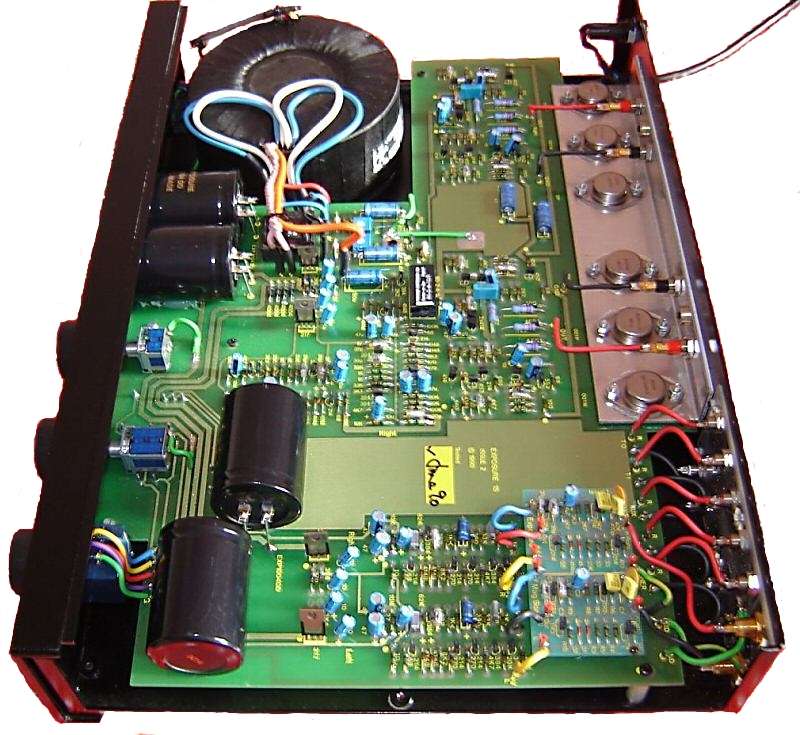
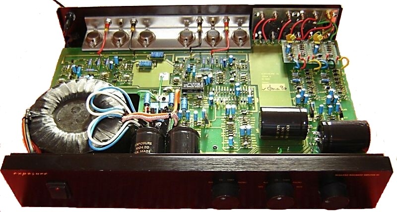
- Holden and Fisher 160VA transformer approx. 2x35V sec.
- Epoxy resin PCB, double sided traces, hand soldered, ultrasonically cleaned
- volume control ALPS RK27112 (blue)
- stabilized power amp voltage via Exposure-assembled power transistors (custom-made 25A TO3 types; at the cooling bracket in the middle there are the 2 complementary line transistors for the operating voltage regulation of both channels, to the right and to the left there are a pair of complementary power transistors each screwed in compound circuit for the power amp outputs)
- Exposure-terminated 10000µF main power supply capacitors
- Use of higher quality Philips (BC) capacitors for all electrolytic capacitors
- gold plated chinch sockets in the phono input
- very low quiescent current of the power amplifiers (very small Class-A range, low no-load power), nevertheless low distortion due to compound power amplifier circuit (the power transistors are connected to the output at the collector)
- very high quality aluminium enclosure
- tape monitor
Remarks
This is a further development of the Exposure X, designed by John Farlowe. The Exposure XV is a typical English amplifier and has very conventional, discrete amplifier circuits with bipolar transistors. Particular attention was paid to the supply of the individual stages with a voltage as independent of load or frequency response as possible within the budget, moderately high negative feedback, a defined grounding and the use of small components in the signal path with as little mass as possible (e.g. 10µF coupling capacitors). For operation, the manufacturer recommended the use of in-house loudspeaker cables (similar or identical in construction to Naim, Linn K20 etc...). This makes sense from a circuit point of view, the very simple output circuit without filter elements (e.g. air coil) is not designed for high capacitive loads, which have a negative effect on the sound via the negative feedback loop of the power amplifier. The Exposure XV was developed on the basis of the Exposure X, especially because of its high noise level resulting from the power supply circuit, but also because of the very loud switch-on pop. The reason why the power-on pop is perceived in both units is that, for reasons of sound quality and durability, no power-on delay with loudspeaker relay is used. In the case of the Exposure X the preamplifier voltage was taken from the main power supply, but the input ground was completely separated from the loudspeaker ground, the coupling was only done via the operating voltages. This way the amplifier showed better dynamic distortion values than when the grounds were coupled. However, this also meant that potential shifts between input and output ground caused by component tolerances could lead to excessive power-on popping, and the noise of the voltage regulators was also in series with the line signal. Essential innovations of the Exposure XV are therefore
- a switch-on delay that applies the line signal to the power amp input only after the preamp equalization processes have died down,
- an additional transformer winding, from which the preamplifier is extra supplied with an additional rectifier and another pair of the Exposure slotted film electrolytic capacitors, which are decisive for the sound.
Input and output ground are connected, noise is lower than with the Exposure X, though not gone. The sound can be described as very musical, in view of the low continuous power incredibly(!) powerful and dynamic. Externally the XV differs from the X by
- the rotary switches,
- simpler cabinet design with brushed, dark aluminium front and * newer company logo.
- newer company logo.
Transistors Used
- Phono, Line stage:
- ZTX214, ZTX384 high-noise type, similar/same BC214/BC384 design.
- Power supply:
- ZTX452,ZTX552, 100V;1.5A;hfe approx. 100
EXP8N, EXP8P, for power amplifiers, similar to MJ15003/MJ15004.
- Output stage:
- BC414B hfe approx. 200 for current source differential input, high-noise type.
- BC414C hfe approx. 450 for differential input, high-noise type
- ZTX452,ZTX552, for voltage amplifier, driver, see above.
- EXP1N, EXP1P, for power amplifiers, similar in design to MJ15003/MJ15004
Other models of the same series:
- Exposure X
- Exposure XX (identical in construction to Exposure XV, but without phono section)
Repair tips In the case of a short-circuit, it is usually not the output stages that go wrong first, but the voltage stabilisation. Here it is especially the driver transistors (next to the central ground point) that get continuity. In this state the unit can function for a long time more bad than good, but due to the (mostly one-sided) higher operating voltage the voltage amplifier stage is thermally overloaded, so that in case of its failure the amplifier usually breaks down to an operating voltage (high DC voltage at the output). The operating voltage can be checked directly at the TO3 packages (collector) of the two middle output transistors opposite the central ground point (tinned island with screw near the corner of the transformer recess, short green cable, green ground cable from below) and should be in the range of 33V (+/-5%, it can be precisely adjusted at the two trim potentiometers next to the central ground point when the unit is intact). When replacing the drivers, first carefully desolder both sides with desoldering suction wire, as it is easy to tear off the solder lugs. If the output or control transistors are really defective, you can help yourself with MJ15003/15004, there is hardly any difference in sound, especially if you select the complementary pairs to about the same current gain. Please do not tighten the screws too much.
- The transistor types ZTX452/ZTX552 can be replaced with BC639/BC640 (less voltage resistant, only 80V, but usable in this unit!), or you can use the very similar and still (2008) available ZTX653/ZTX753.
When replacing the smaller electrolytic capacitors, e.g. 105°C Panasonic FC types have proven themselves, especially the electrolytic capacitors near the voltage regulators often show wear due to the higher temperature there.


