Difference between revisions of "JVC A-X 5"
Mindtwister (talk | contribs) |
m (→Pictures) |
||
| (3 intermediate revisions by 2 users not shown) | |||
| Line 74: | Line 74: | ||
| + | [[File:C:\Users\luise\Pictures\JVC\A-X5\A-X5|thumb]] | ||
== Pictures == | == Pictures == | ||
| + | * Picture: JVC A-X 5 | ||
| + | https://hifi-wiki.com/images/archive/6/67/20241118014351%21C--Users-luise-Pictures-JVC-A-X5-A-X5.png | ||
| + | |||
| + | |||
| + | * Picture: JVC A-X 5 | ||
| + | https://hifi-wiki.com/images/6/67/C--Users-luise-Pictures-JVC-A-X5-A-X5.png | ||
| + | |||
| + | |||
* Picture: JVC A-X 5 | * Picture: JVC A-X 5 | ||
http://www.hifi-wiki.de/images/7/7b/JVC_A-X5_front_2.jpg | http://www.hifi-wiki.de/images/7/7b/JVC_A-X5_front_2.jpg | ||
Latest revision as of 20:50, 17 November 2024
Data
General:
- Manufacturer: JVC
- Model: A-X 5
- Type: Super-A integrated amplifier
- Years of manufacture: 1979 - 1981
- Made in: Japan
- Color: Silver
- Remote control: no
- Power consumption: 500 W max.
- Dimensions: 450 x 140 x 420 mm (WxHxD)
- Weight: 11,5 kg
- Original price approx.: 1'150 DM (list price)
Connections:
- Inputs:
- 2x Phono (MM or MC)
- Phono MM : 2.5 mV/ 47 kOhm (max. 250 mV)
- Phono MC : 0.2 mV/ 100 Ohm (max. 18 mV)
- Tuner, Aux, Tape 1, 2: 200 mV/ 47 kOhm.
- Outputs:
- Tape 1,2 Rec Out: 200 mV/ 680 Ohm.
- 2 pairs of speakers
- Headphones
Technical Data:
- Continuous output power
- 8 Ohm: 2 x 70 Watt (8 Ohm, 20- 20.000 Hz, THD: 0,007 %)
- Dynamic power
- 8 Ohm: ~ 2 x 100 Watt
- Intermodulation distortion:
- 0.004% (60 Hz: 7 kHz = 4:1) at 70 watts,8 ohms.
- Attenuation factor:
- 75 (1 kHz,8 ohms)
- Frequency response: DC - 100 kHz +0, -3 dB
- Power bandwidth : 5- 70,000 Hz
- RIAA MC +- 0.3 dB, 20- 20,000 Hz
- RIAA MM +- 0.2 dB, 20- 20,000 Hz
- Signal-to-noise ratios MC/ MM/ Line: 70 dB/ 85 dB/ 110 dB
- Tone control: Yes
Bass: +- 8 dB at 100 Hz Treble: +- 8 dB at 10,000 Hz
- Loudness: switchable, adjustable
- Subsonic: switchable, 18 Hz - 6 dB/ Oct.
- Muting: switchable, -20 dB
Special features:
- DC-Servo phono preamplifier
- Super-A output stages
- 3-stage DC construction with passive preamplifier
- fully discrete construction of the audio electronics
Notes
- Other models in the same series:
- Integrated amplifiers:
- JVC A-X 1
- JVC A-X 2
- JVC A-X 3
- JVC A-X 4
- JVC A-X 5
- JVC A-X 7
- JVC A-X 9
Pictures
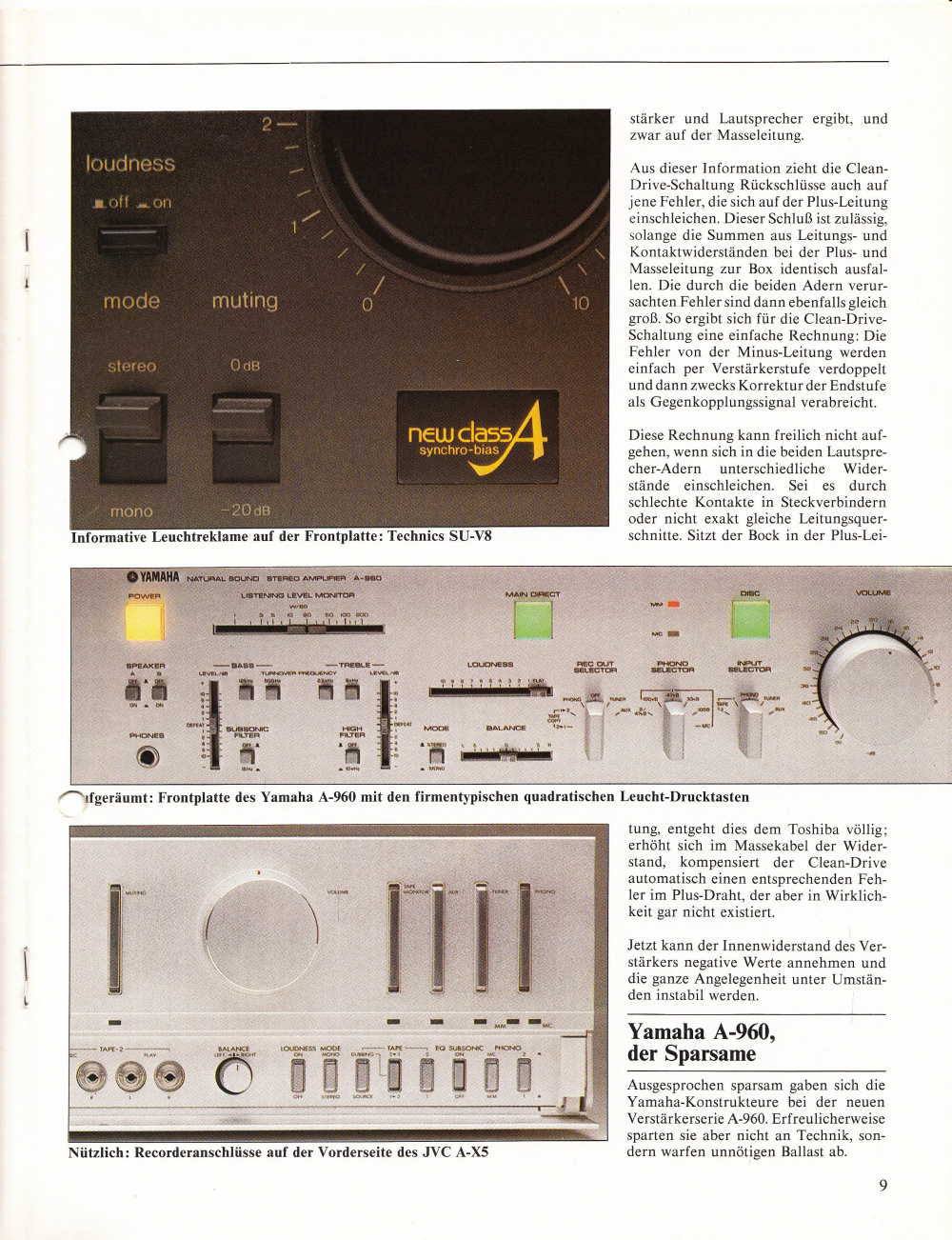
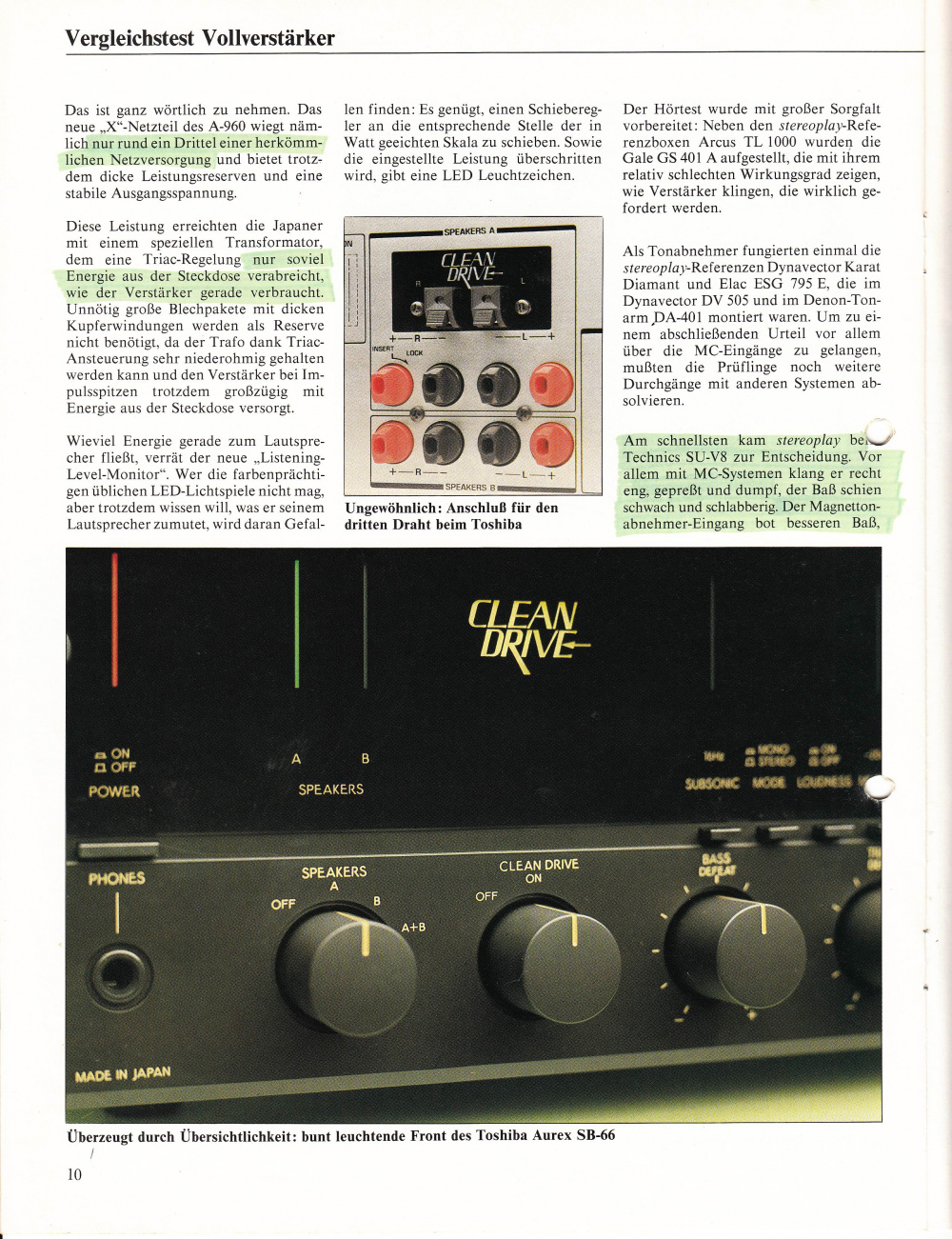
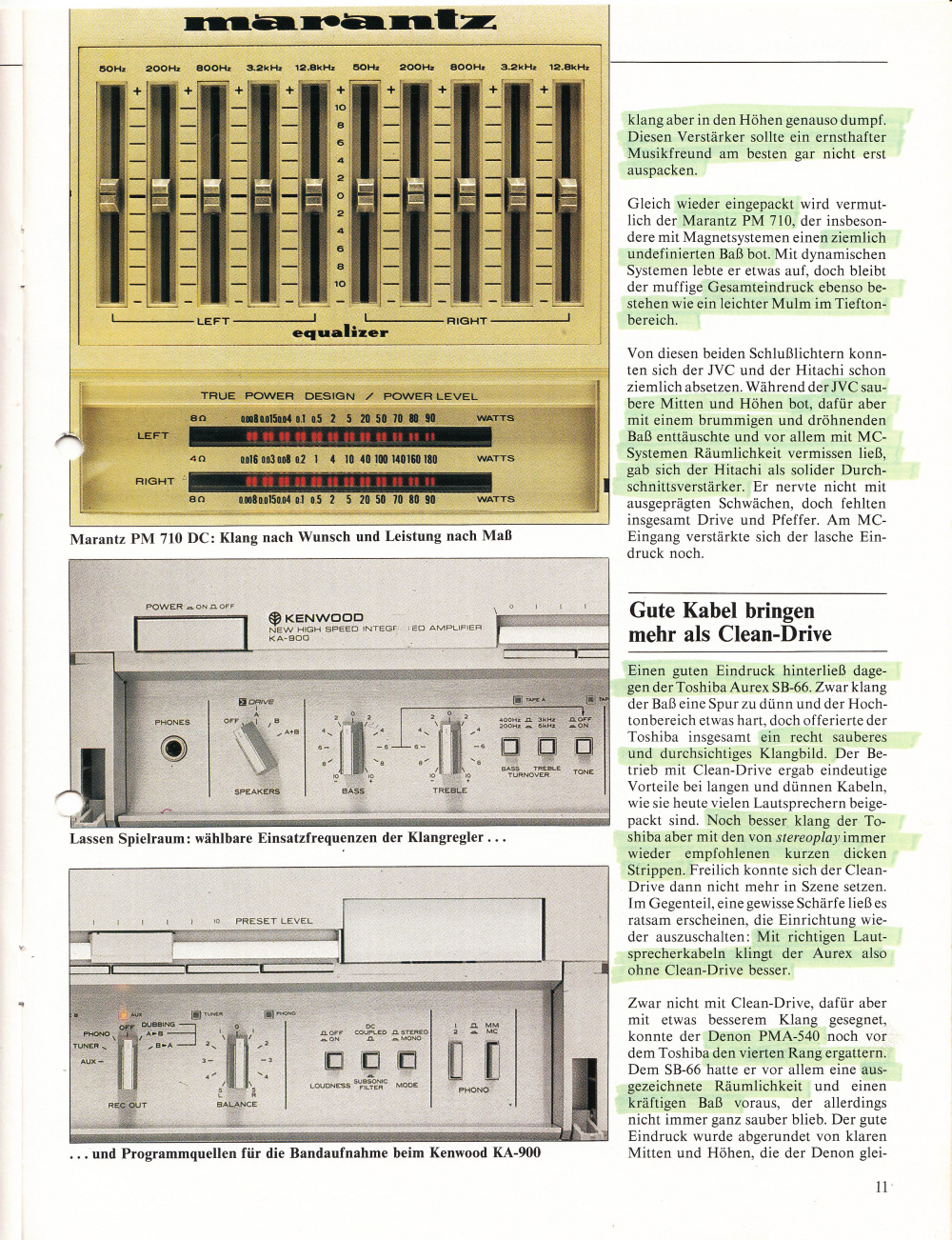
- Picture: JVC A-X 5
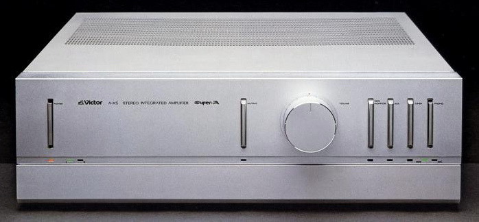
- Picture: JVC A-X 5
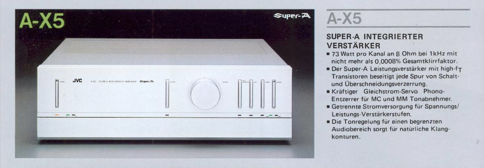
- Picture: JVC A-X 5

- Picture: JVC A-X 5

Tests
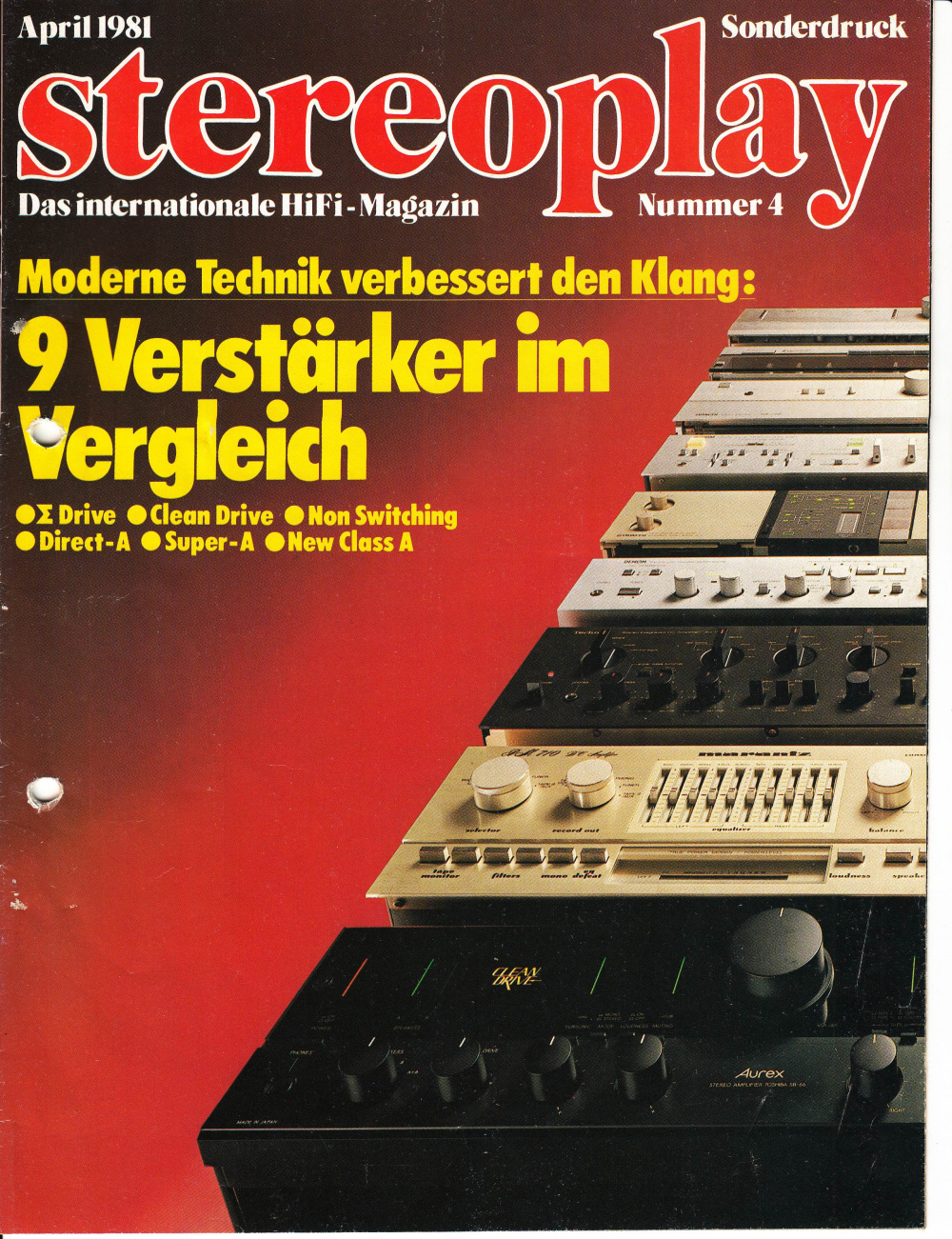
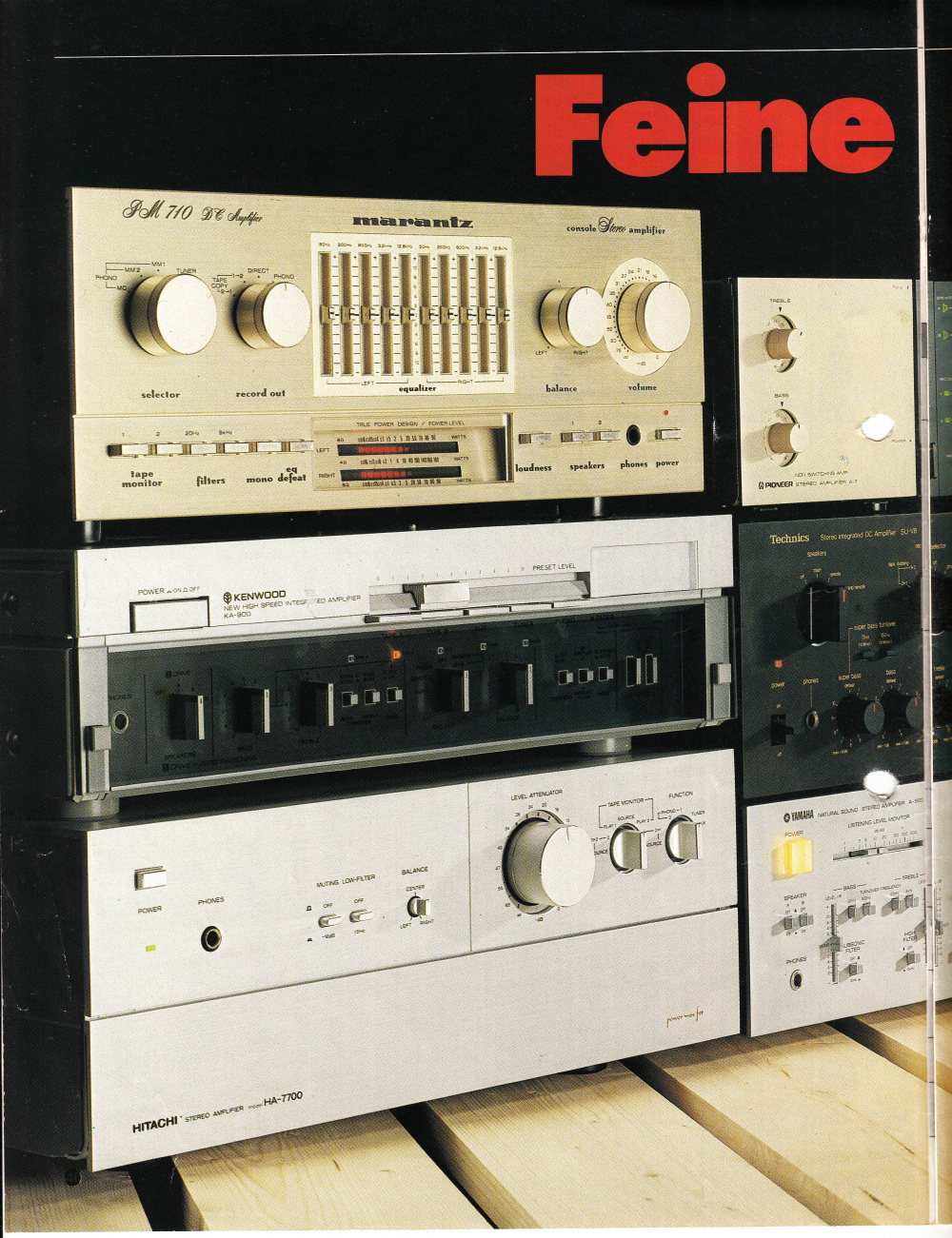
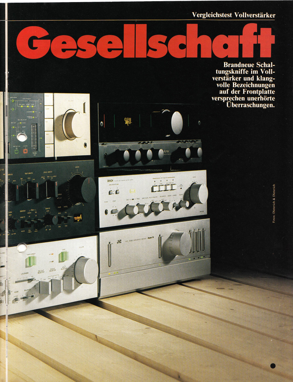
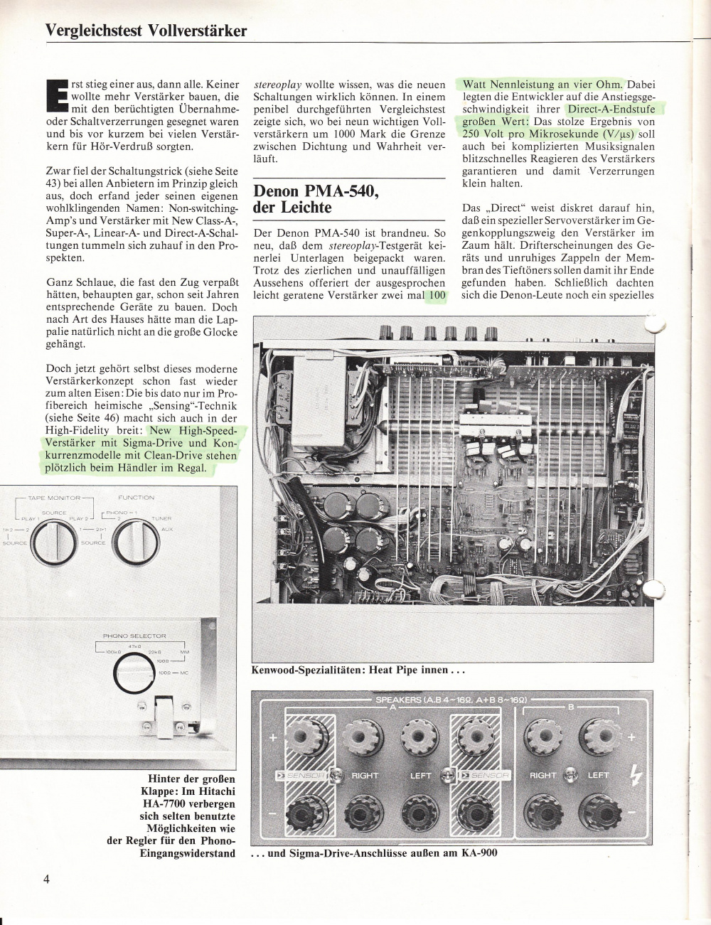
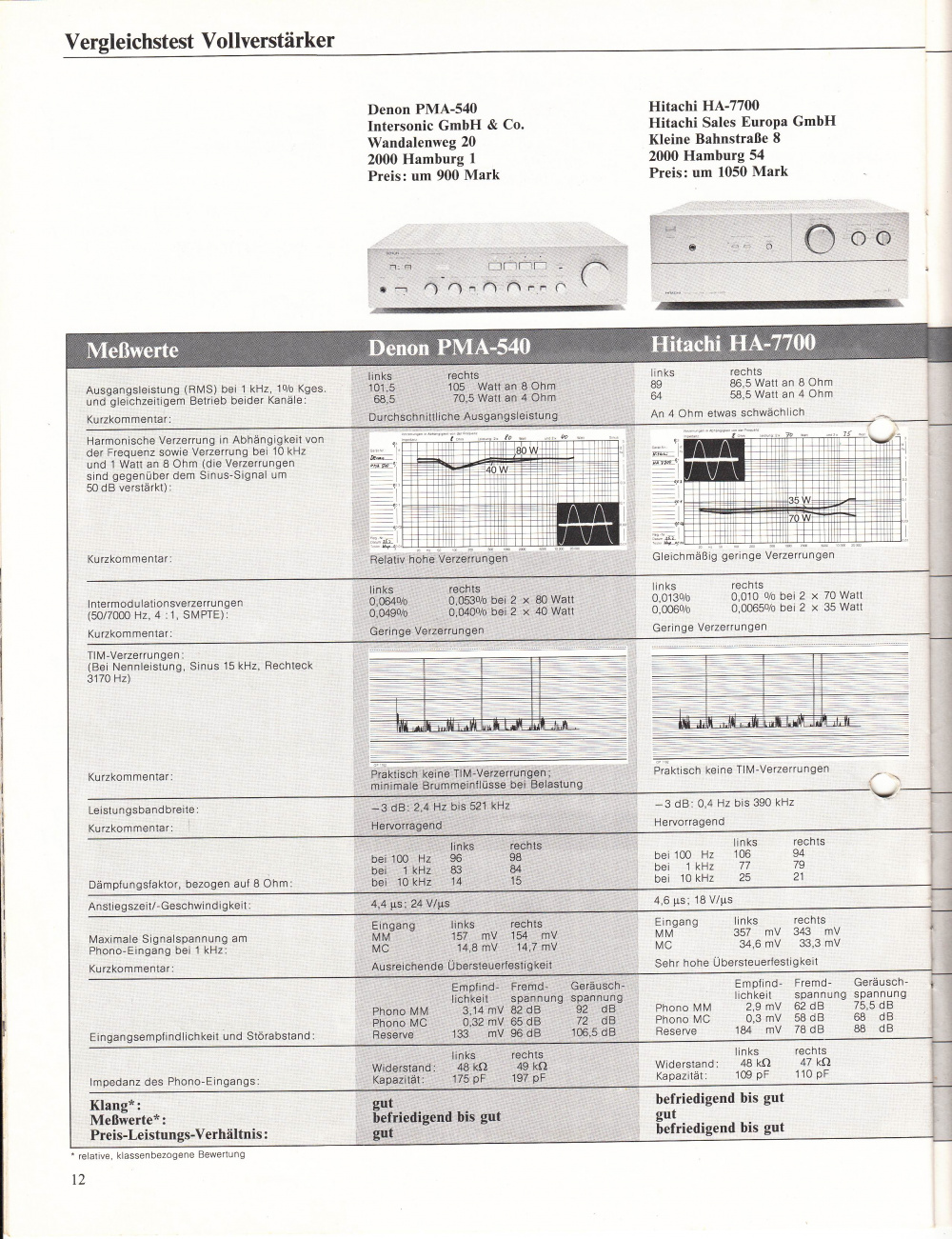
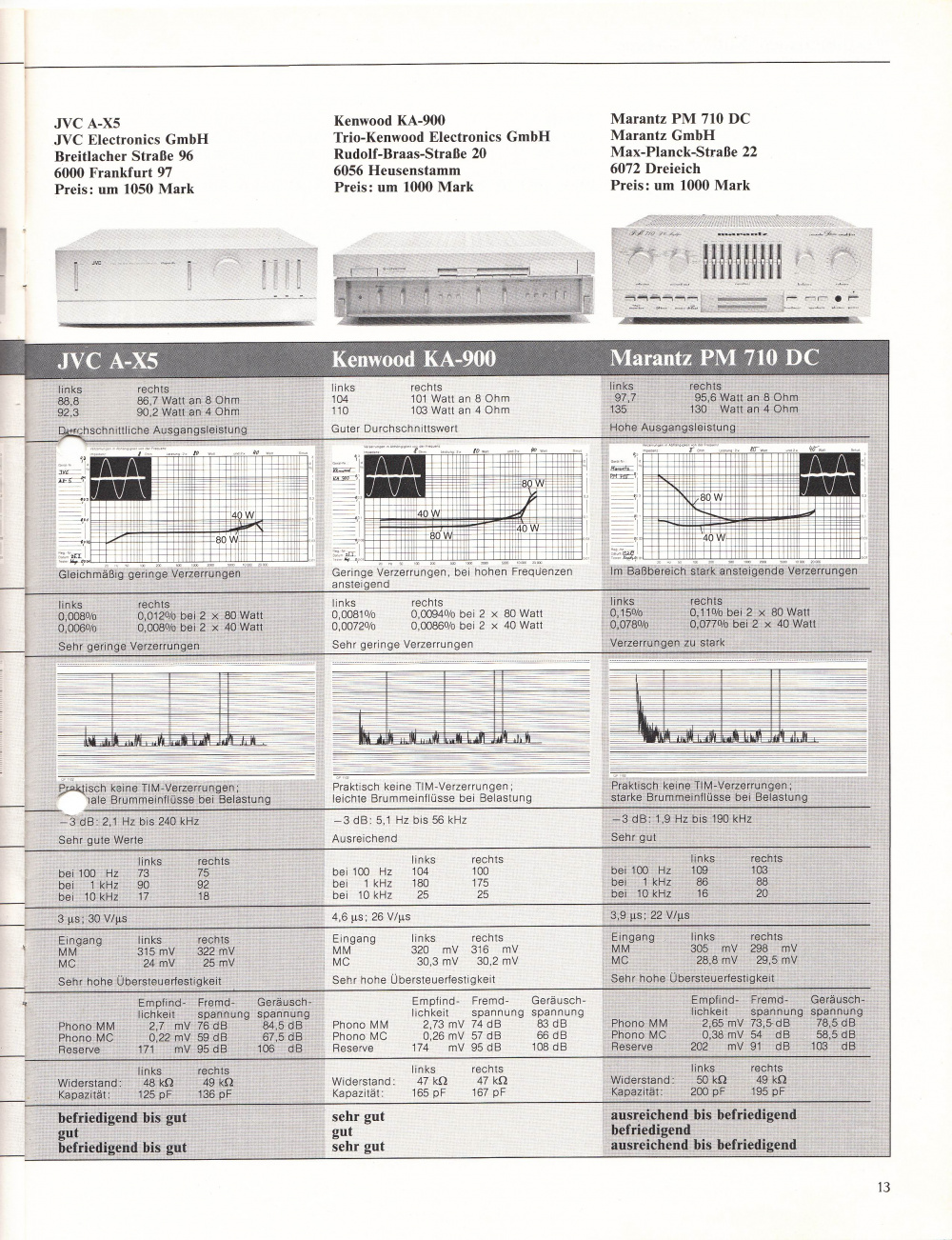
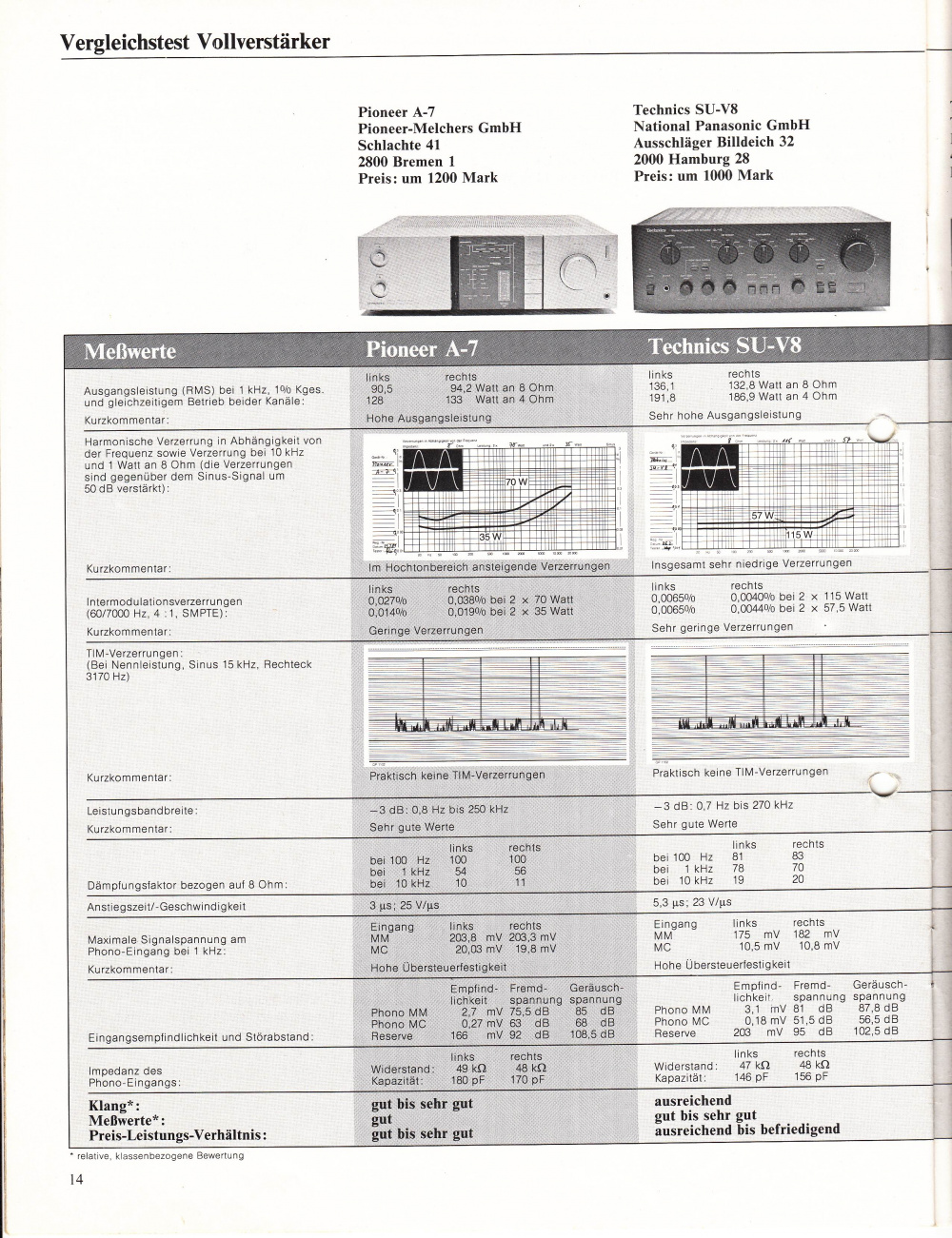
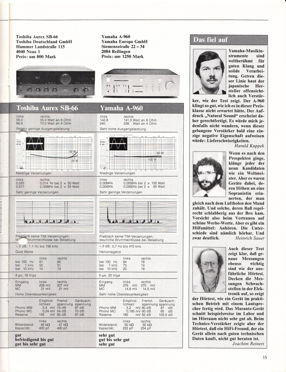
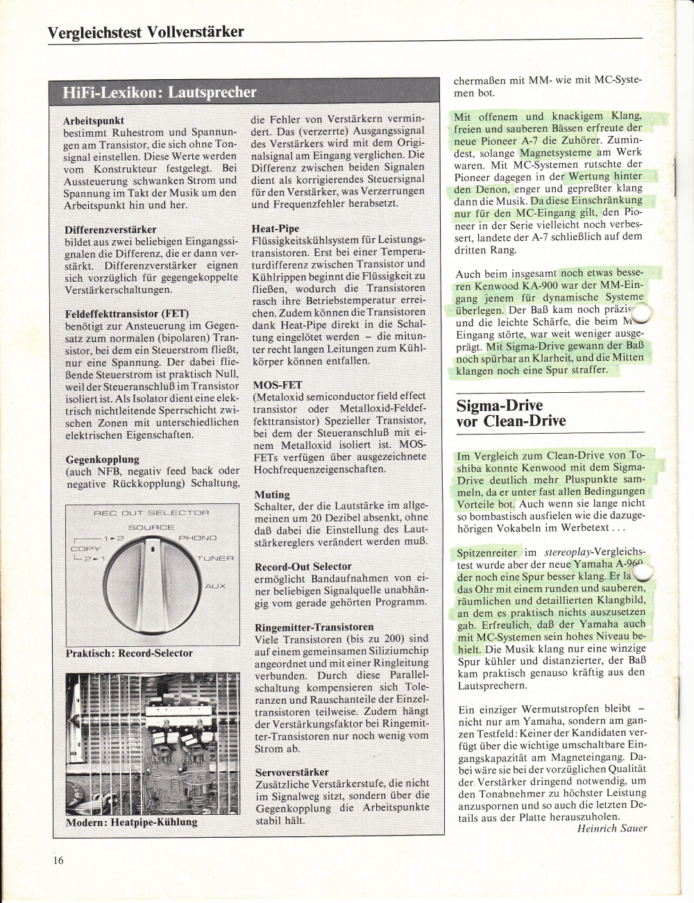
- Stereoplay April 1981 9 amplifiers in comparison
Reports
- Quite rare integrated amplifier from the late seventies by JVC in the then fashionable pseudo-puristic front flap design.
- Compared to the big brother A-X9 noticeably slimmed down in terms of haptics, internal design and circuit luxury equipment, but compared to this hardly impoverished quality by a sophisticated and well-equipped audio electronics, which is currently an average "high-end" integrated amplifier of the 1500 € class would be good to face - but then ultimately not offered there.
The silicon and circuitry used in the A-X5 is, from today's point of view, simply exquisite, for example: 2SK146 JFETs in the phono preamplifier, 2SK150 JFETs in the Class-A driver stage and 2SC2525L/ 2SA1075 RETs as output stage.
- Zero electrolytic capacitors in signal path and a true DC design not only of individual amplifier stages but of the entire device.
- The only coupling capacitors are a couple of oversized PP foil C's at the output of the Phonopre`s.
The whole thing runs at +- 50V and has a bandwidth that would make the amp usable as an HF amplifier. Separate transformer windings for phonopre and driver stage. 2 x 6800 µF charging electrolytic capacitors per channel for the output stages and complex voltage regulators for the preamplifiers. Everything is of course fully discrete. Of course the A-X5 needs a fresh set of electrolytic capacitors after 34 years, but thanks to the careful design of the circuitry, the amount of capacitors is manageable.
- On the negative side, the A-X5 offers quite modest crosstalk attenuation between inputs and is not exactly low impedance stable.
- In this respect a typical Seventies amp, which should not be concealed here.
