Difference between revisions of "Kenwood KA-76"
| (One intermediate revision by the same user not shown) | |||
| Line 1: | Line 1: | ||
__NOTOC__ | __NOTOC__ | ||
| − | == | + | == Data == |
| − | {{ | + | {{navigation}} |
| − | ''' | + | '''General''' |
| − | * | + | * Manufacturer: [[Kenwood]] |
| − | * | + | * Model: KA-76, component of the overall system [[Kenwood V-76]] |
| − | * | + | * Type: Integrated amplifier |
| − | * | + | * Years of manufacture: July 1987 - 1988 |
| − | * | + | * Made in: Japan |
| − | * | + | * Colour: Black |
| − | * | + | * Remote control: no |
| − | * | + | * Power consumption: |
| − | * | + | * Dimensions: 420 x 110 x 277 mm (WxHxD). |
| − | * | + | * Weight: 7.2 kg |
| − | * | + | * Original price approx.: 398 DM (RRP) |
| − | ''' | + | '''Connections''' |
| − | * | + | * Number of inputs: |
** CD, Tuner, 2x Tape, Aux, Phono | ** CD, Tuner, 2x Tape, Aux, Phono | ||
| − | * | + | * Number of outputs: |
** Tape rec out | ** Tape rec out | ||
| − | ''' | + | '''Technical data''' |
| − | |||
| − | |||
| − | |||
| − | |||
| − | |||
| − | |||
| − | |||
| − | |||
| − | |||
| − | |||
| − | |||
| − | |||
| − | |||
| − | |||
| − | |||
| − | |||
| − | |||
| − | |||
| − | |||
| + | [[File:Kenwood KA- Daten-1987.jpg]] | ||
| − | |||
| − | |||
| + | '''Special Features''' | ||
| + | * Switching of the power supply voltage to match the speaker impedance 4/8 ohms. | ||
| − | == | + | |
| − | * | + | == Remarks == |
| − | * | + | * Other models in the same series: |
| + | * Amplifier: | ||
* [[Kenwood KA-56]] | * [[Kenwood KA-56]] | ||
* [[Kenwood KA-76]] | * [[Kenwood KA-76]] | ||
| Line 60: | Line 43: | ||
| − | == | + | == Pictures == |
| − | * | + | * Picture: Kenwood KA-76 |
| − | [[ | + | [[Image:Kenwood_KA-76.jpg]] |
| − | * | + | * Picture: Kenwood KA-76 |
| − | [[ | + | [[Image:Kenwood-KA76-open.jpg]] |
| − | * | + | * Excerpt from brochure: Kenwood KA-76 |
| − | [[ | + | [[File:Kenwood KA-56-76-KT-56 L-Prospekt-1987.jpg]] |
| − | == | + | == Reports == |
| − | * | + | * Unit was refurbished in 1999 with 2SC3281/2SA1302. In 2010 the power amplifier was destroyed by connecting defective speakers on this occasion it was found that the 2SA3201 were fakes. Chip size only 1/3 of the 2SC3281. In the operating mode 4 Ohm the device was stable for years at full load. |
| − | * | + | * Besides the transistors, the emitter resistors and the 330R, 22R and 2.2R safety resistors were defective. The driver stage was still intact. The picture below shows the restored power amp with the following replacements: |
| − | ** | + | ** new safety resistors 0,5W |
| − | ** | + | ** new emitter resistors MPC725 |
| − | ** | + | ** new output transistors MJL4281AG / MJL4302AG |
| − | ** | + | ** flat milled surface on heat sink |
| − | ** 1 | + | ** 1.8k, 470R and ZD16V at left front board edge rebuilt to higher power handling, cooling fin at 1k8 resistor retrofitted. |
| − | == | + | == Left == |
| − | [[ | + | [[Category:Integrated amplifier]] |
Latest revision as of 10:11, 22 March 2021
Data[edit]
General
- Manufacturer: Kenwood
- Model: KA-76, component of the overall system Kenwood V-76
- Type: Integrated amplifier
- Years of manufacture: July 1987 - 1988
- Made in: Japan
- Colour: Black
- Remote control: no
- Power consumption:
- Dimensions: 420 x 110 x 277 mm (WxHxD).
- Weight: 7.2 kg
- Original price approx.: 398 DM (RRP)
Connections
- Number of inputs:
- CD, Tuner, 2x Tape, Aux, Phono
- Number of outputs:
- Tape rec out
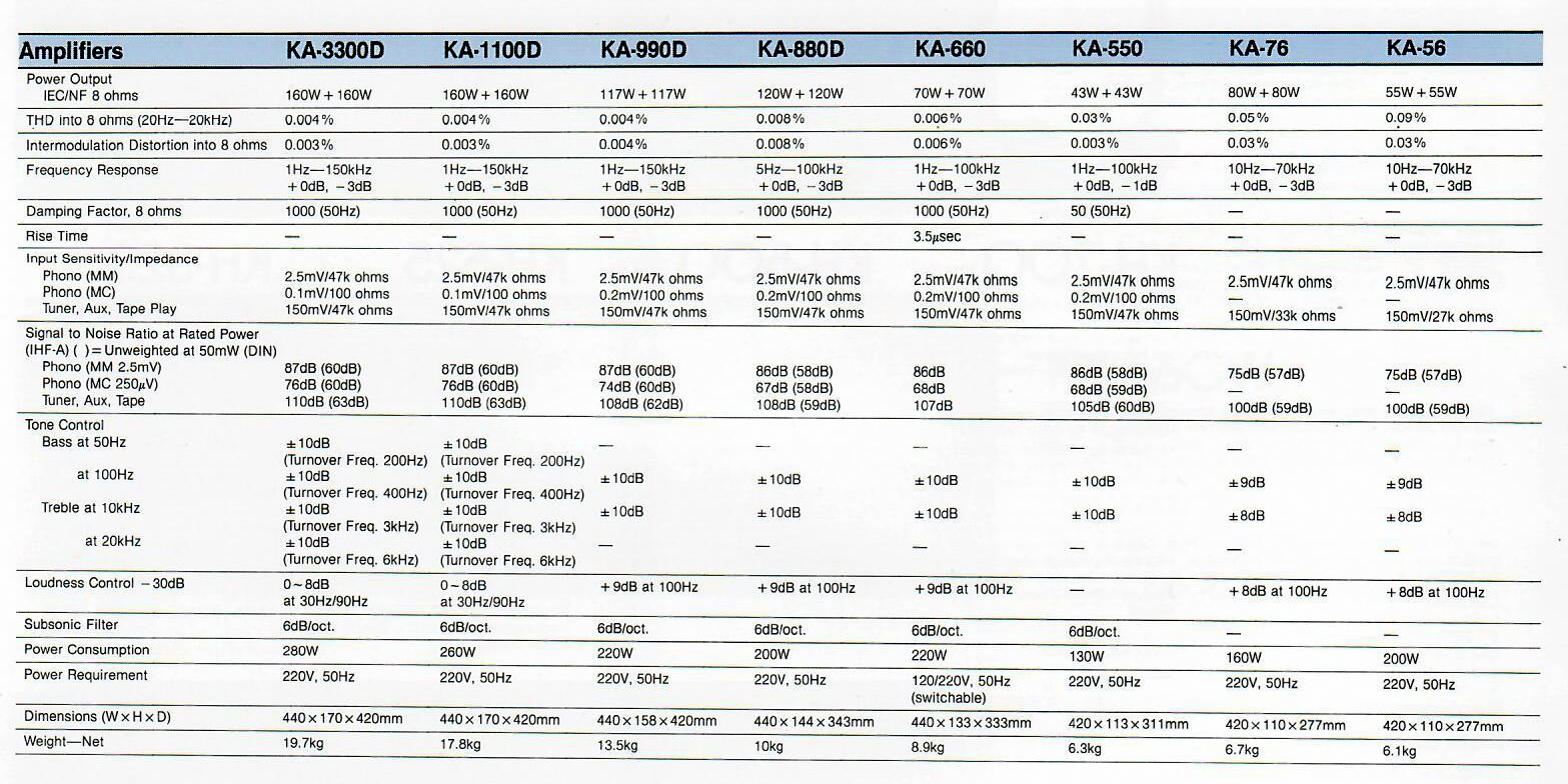
Technical data
Special Features
- Switching of the power supply voltage to match the speaker impedance 4/8 ohms.
Remarks[edit]
- Other models in the same series:
- Amplifier:
- Kenwood KA-56
- Kenwood KA-76
- Tuner:
- Kenwood KT-56 L
Pictures[edit]
- Picture: Kenwood KA-76
- Picture: Kenwood KA-76
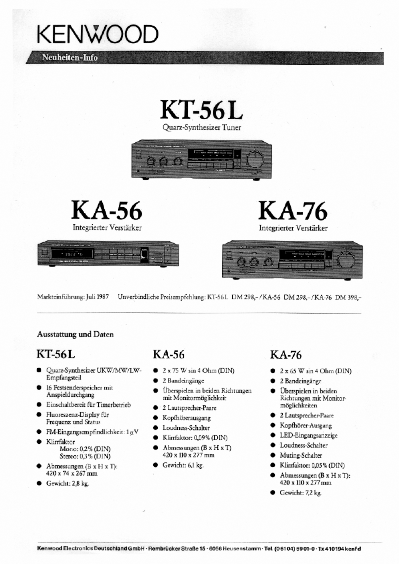
- Excerpt from brochure: Kenwood KA-76
Reports[edit]
- Unit was refurbished in 1999 with 2SC3281/2SA1302. In 2010 the power amplifier was destroyed by connecting defective speakers on this occasion it was found that the 2SA3201 were fakes. Chip size only 1/3 of the 2SC3281. In the operating mode 4 Ohm the device was stable for years at full load.
- Besides the transistors, the emitter resistors and the 330R, 22R and 2.2R safety resistors were defective. The driver stage was still intact. The picture below shows the restored power amp with the following replacements:
- new safety resistors 0,5W
- new emitter resistors MPC725
- new output transistors MJL4281AG / MJL4302AG
- flat milled surface on heat sink
- 1.8k, 470R and ZD16V at left front board edge rebuilt to higher power handling, cooling fin at 1k8 resistor retrofitted.


