Difference between revisions of "Elac 3100 T"
| (2 intermediate revisions by the same user not shown) | |||
| Line 1: | Line 1: | ||
__NOTOC__ | __NOTOC__ | ||
| − | == | + | == Data == |
| − | {{ | + | {{navigation}} |
| − | ''' | + | '''General''' |
| − | * | + | * Manufacturer: [[Elac]] |
| − | * | + | * Model: 3100 T |
| − | * | + | * Type: Receiver |
| − | * | + | * Years of manufacture: 1967 - 1968 |
| − | * | + | * Made in: Germany |
| − | * | + | * Color: front silver / black, housing walnut |
| − | * | + | * New price approx: see technical data |
| − | ''' | + | '''Technical data''' |
| − | [[ | + | [[File:Elac 3100 T-Daten1.jpg]] |
| − | [[ | + | [[File:Elac 3100 T-Daten1.jpg]] |
| − | == | + | == Comments == |
| − | * | + | * Other models in the same series: |
* Receiver: | * Receiver: | ||
* [[Elac 3100 T]] | * [[Elac 3100 T]] | ||
| − | * | + | * Record player: |
| + | * [[Elac Miraphon 20]] | ||
| + | * [[Elac Miraphon 22 H]] | ||
| + | * [[Elac Miracord 40]] | ||
| + | * [[Elac Miracord 50 H]] | ||
| + | |||
| + | |||
| + | * [[Loudspeaker]]: | ||
| + | * [[Elac LK 30]] | ||
| + | * [[Elac LK 100]] | ||
* [[Elac LK 3100]] | * [[Elac LK 3100]] | ||
| − | == | + | == Pictures == |
| − | * | + | * Image: Elac 3100 T |
| − | [[ | + | [[File:Elac 3100 T-Daten1.jpg]] |
| − | * | + | * Excerpt from brochure: Elac 3100 T, LK 3100 |
| − | [[ | + | [[File:Elac LK-3100-Prospekt-1.jpg]] |
| − | == | + | == Reports == |
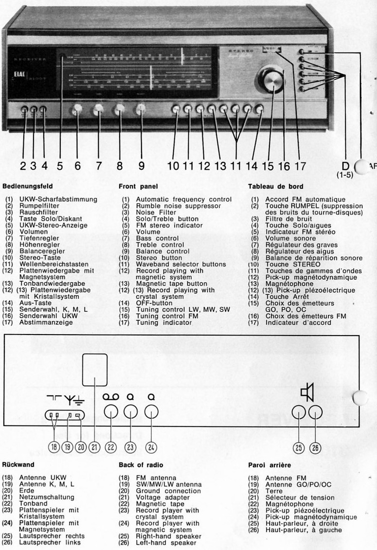
| − | * | + | * Extract from brochure: Elac 3100 T controls |
| − | [[ | + | [[File:Elac 3100 T-Daten1.jpg]] |
| − | * | + | * Other data, especially for repairing old ELAC receivers 3100 T are: Scale lamps E10 screw thread 4* 7V 0.3A and stereo lamp 3.8V 0.07A, which can be exchanged for some other types, like 4* 6.3V 0.3A and 4V 0.1A or 6V 0.05A. |
| − | * | + | * Power stage transistors vary and can be AL102, AD150, AD166 or 2N2148. After transistors have been changed in the power amp, a quiescent current adjustment should be made using a potentiometer (500 ohms). This is located on the power stage heat sink. |
| − | + | Each output stage consists of two transistors. If only one of the transistors is defective, the other one must also be replaced, as it cannot be assumed that it will still function properly. You can often buy power amp transistors measured and as a pair of two. | |
| − | * | + | * The following are suitable as driver transistors: AC116K, AC124K, and AC188K. Pre-stage transistors like BC109 can be replaced by BC107, BC108 or equivalent low noise types. |
| − | + | Transistors AC132 should only be replaced by AC152, because some AC132 are used as hot leads in the output stage and therefore have special characteristics. | |
| − | * | + | * Transistors designated 2SB257 or TF66 can be exchanged for a variety of other transistors, such as AC122, AC125, AC126, AC131, AC150, AC152 and AC161. Similarly, the AC150 is interchangeable with a variety of the listed transistors. |
| − | * | + | * The following transistors SFT351 and SFT353 are mostly installed on the stereo decoder and control the stereo lamp. They can be exchanged for so many types that I will not list all types here. But roughly it can be said that the transistors must withstand at least 0.15A and 25 volts. |
| − | * | + | * High frequency transistors, like AF121, AF124, AF125, AF126 and AF137 are usually not to be exchanged. If swapping is necessary, types such as AF114, AF127, AF134, AF136, AF138, and possibly AF139 should be used. There are some differences in transistors, such as AM and FM transistors and some are specifically for IF. One should collect here some information about the transistors and then make an exchange against an equivalent type with the same characteristics. |
| − | * | + | * All these old germanium transistors are not produced anymore, but you can get them in some online shops, like EBay, Little Diode or partly via radio/TV repair shops. You can expect prices from 1 to 4 Euro per piece depending on the transistor type. |
| − | * | + | * All soldering work on the receiver should be done with Radiolot. '''Additional fluxes should not be used for soldering under any circumstances, since they are often acidic and thus aggressive.'' This can lead to corrosion of conductors, as well as cause interference in the receiver. Disturbances are usually noticeable as hissing, crackling or other noises in the loudspeaker. |
| − | + | CAUTION when working on an open receiver: When using mains power, the metal chassis should be earthed as it is live. The voltage applied to the chassis comes from two suppressor capacitors which are connected between the mains voltage and the chassis. Normally the voltage of the chassis should not be lethal, because the current is low, but if one of the capacitors gets a short circuit, then there is danger of life! | |
| − | * '' | + | * ''If needed, I will also post a scanned schematic of the receiver here, as long as this does not violate any legal regulations or copyrights.'' |
| Line 72: | Line 81: | ||
| − | [[ | + | [[Category:Receiver]] |
Latest revision as of 01:04, 16 May 2020
Data
General
- Manufacturer: Elac
- Model: 3100 T
- Type: Receiver
- Years of manufacture: 1967 - 1968
- Made in: Germany
- Color: front silver / black, housing walnut
- New price approx: see technical data
Technical data
Comments
- Other models in the same series:
- Receiver:
- Elac 3100 T
- Record player:
- Elac Miraphon 20
- Elac Miraphon 22 H
- Elac Miracord 40
- Elac Miracord 50 H
Pictures
- Image: Elac 3100 T
- Excerpt from brochure: Elac 3100 T, LK 3100
Reports
- Extract from brochure: Elac 3100 T controls
- Other data, especially for repairing old ELAC receivers 3100 T are: Scale lamps E10 screw thread 4* 7V 0.3A and stereo lamp 3.8V 0.07A, which can be exchanged for some other types, like 4* 6.3V 0.3A and 4V 0.1A or 6V 0.05A.
- Power stage transistors vary and can be AL102, AD150, AD166 or 2N2148. After transistors have been changed in the power amp, a quiescent current adjustment should be made using a potentiometer (500 ohms). This is located on the power stage heat sink.
Each output stage consists of two transistors. If only one of the transistors is defective, the other one must also be replaced, as it cannot be assumed that it will still function properly. You can often buy power amp transistors measured and as a pair of two.
- The following are suitable as driver transistors: AC116K, AC124K, and AC188K. Pre-stage transistors like BC109 can be replaced by BC107, BC108 or equivalent low noise types.
Transistors AC132 should only be replaced by AC152, because some AC132 are used as hot leads in the output stage and therefore have special characteristics.
- Transistors designated 2SB257 or TF66 can be exchanged for a variety of other transistors, such as AC122, AC125, AC126, AC131, AC150, AC152 and AC161. Similarly, the AC150 is interchangeable with a variety of the listed transistors.
- The following transistors SFT351 and SFT353 are mostly installed on the stereo decoder and control the stereo lamp. They can be exchanged for so many types that I will not list all types here. But roughly it can be said that the transistors must withstand at least 0.15A and 25 volts.
- High frequency transistors, like AF121, AF124, AF125, AF126 and AF137 are usually not to be exchanged. If swapping is necessary, types such as AF114, AF127, AF134, AF136, AF138, and possibly AF139 should be used. There are some differences in transistors, such as AM and FM transistors and some are specifically for IF. One should collect here some information about the transistors and then make an exchange against an equivalent type with the same characteristics.
- All these old germanium transistors are not produced anymore, but you can get them in some online shops, like EBay, Little Diode or partly via radio/TV repair shops. You can expect prices from 1 to 4 Euro per piece depending on the transistor type.
- All soldering work on the receiver should be done with Radiolot. 'Additional fluxes should not be used for soldering under any circumstances, since they are often acidic and thus aggressive. This can lead to corrosion of conductors, as well as cause interference in the receiver. Disturbances are usually noticeable as hissing, crackling or other noises in the loudspeaker.
CAUTION when working on an open receiver: When using mains power, the metal chassis should be earthed as it is live. The voltage applied to the chassis comes from two suppressor capacitors which are connected between the mains voltage and the chassis. Normally the voltage of the chassis should not be lethal, because the current is low, but if one of the capacitors gets a short circuit, then there is danger of life!
- If needed, I will also post a scanned schematic of the receiver here, as long as this does not violate any legal regulations or copyrights.

